⚡ TL;DR
- UML takes a long time to learn, especially with 14 diagram types. The good news is that there are many alternatives.
- SysML is a branch of UML 2 geared toward software-oriented systems. It includes 9 diagram types and can be used to map hardware, software, and processes.
- The C4 model is a lightweight modelling language with 4 levels of hierarchy and a limited set of abstractions at each level. It strikes a good balance between detail and simplicity.
- Other alternatives, like BPMN and entity-relationship diagrams, are useful for specific use cases. Consider them as complementary methods to be used in tandem with another modelling language.
🚀 Introduction
Unified Modelling Language (UML) was developed in the late 1990s as the standard method for mapping software systems. As teams, processes, and systems have changed since its creation, so has the need for a modelling language that provides just the right amount of detail that doesn’t get in the way of shipping fast. So, what are the alternatives?
In this article, we’ll talk about a few alternatives to UML — some that were influenced by UML and some that were created as a completely new way of approaching architectural design. What you’ll discover is that many of the alternatives aren’t as comprehensive as UML and focus on a specific use case (like business process or database design). There’s a tradeoff to less complexity. Let’s dive in and see what the options are!
1️⃣ SysML
SysML is a general-purpose modelling language that’s a branch of UML 2 (described as a ‘dialect’ of UML 2; who knew there were modelling language dialects? 😅). Since it’s heavily influenced by UML, it includes a similar set of diagrams, albeit fewer ones than the 15 in UML (9 diagram types). UML 2 extends UML for more software-oriented applications, so you’ll find new and modified diagrams better suited for these types of systems.
Some of the diagram types include:
- Requirement diagrams
- Use case diagrams
- Activity diagrams
- Sequence diagrams
- State machine diagrams
This language supports various system types, from hardware to software, processes, and information.

2️⃣ C4 model
The C4 model is a lightweight modelling language developed by Simon Brown in the mid to late 2000s. It was developed to counter the complexity and heaviness of UML. In the C4 model, there are 4 levels of hierarchy (context, container, component, code), each with a limited set of abstractions (actor, system, app, store, or component).
We’ve talked about the C4 model plenty (we’re big fans of it), so feel free to check out some of our most popular articles:
- https://icepanel.io/blog/2024-07-18-what-is-the-c4-model
- https://icepanel.io/blog/2024-07-29-comparison-c4-model-vs-UML
- https://icepanel.io/blog/2024-08-06-comparison-c4-modelling-vs-diagramming
- https://icepanel.io/blog/2024-09-17-top-5-resources-c4-model

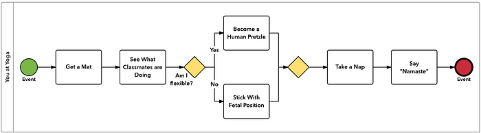
3️⃣ Business process model and notation (BPMN)
Business process model and notation (BPMN) is a flowchart stye language for communicating business workflows. Unlike UML, it focuses on a higher level of abstraction as opposed to the technical implementation of a solution. Instead of highlighting the interactions between different objects in a system (or across systems), it focuses on steps and tasks to improve efficiency.
Nowadays, these diagrams can be easily drawn using diagramming tools like Miro and LucidChart or even by hand. They have a simple notation (basically a combination of boxes, circles, diamonds, lines, and swimlanes) and are easy to learn.
BPMN can complement UML but isn’t a complete alternative. It’s typically used by non-technical people like business analysts or strategists to communicate high-level initiatives with different stakeholders.
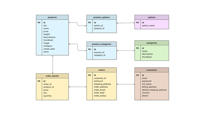
4️⃣ Entity-relationship diagrams (ERDs)
An entity-relationship diagram (ERD) is a lower-level diagram that shows the structure and relationships of a data model. It’s primarily used in database design to help people understand what type of data is stored, how the data is related, and the best way to structure the data before implementation.
These diagrams are typically more useful for technical people planning the implementation of a system. Like BPMN, they cover a small scope of use cases and are better used alongside other modelling languages.
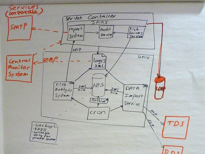
5️⃣ Good old boxes and lines
Sometimes, the best alternative is the simplest one. For quick and dirty architecture diagrams, hand-drawn boxes and lines are a good option. You get maximum flexibility and convenience. It’s also a nice opportunity to step away from screens with your team to think about a problem more tangibly. Just make sure that these ad hoc diagrams get documented officially somewhere if they need to be referenced in the future.